Spark Gap Tesla Coil
 To quote from my SSTC (Solid State Tesla Coil) webpage:
During the early 20th century Nikola Tesla experimented with high voltage high frequency self-resonating air cored transformers. These air cored transformers are now known as Tesla coils.
An SSTC uses modern day techniques to drive the air cored transformer and can provide impressive results. However, the power levels and streamer behaviour of a solid state design is somewhat different to Nikola Tesla's original spark gap design.
Generally spark gap based designs tend to use much higher power levels than solid state designs. Also, a spark gap design is far more forgiving and robust than a solid state design. Tuning a solid state Tesla coil often requires a desoldering pump and a large bag of expensive MOSFETs, whereas tuning a spark gap Tesla coil is just a case of tapping the primary coil at different points.
This page shows my attempt at designing and constructing my first spark gap Tesla coil. The design utilizes a 4 MOT stack power supply and a rotary spark gap. Originally salt water capacitors were to be used, but these were later replaced with a far more practical MMC.
The following sub-sections give the details of the coils construction and demonstrate it working.
 Power Supply
Filtering
Tank Capacitor
Secondary Coil
Spark Gap
Primary Coil
Top Load
RF Ground
Results
Power Supply
Filtering
Tank Capacitor
Secondary Coil
Spark Gap
Primary Coil
Top Load
RF Ground
Results
If you have any questions or comments then feel free to email (craig@craigsarea.com) me.
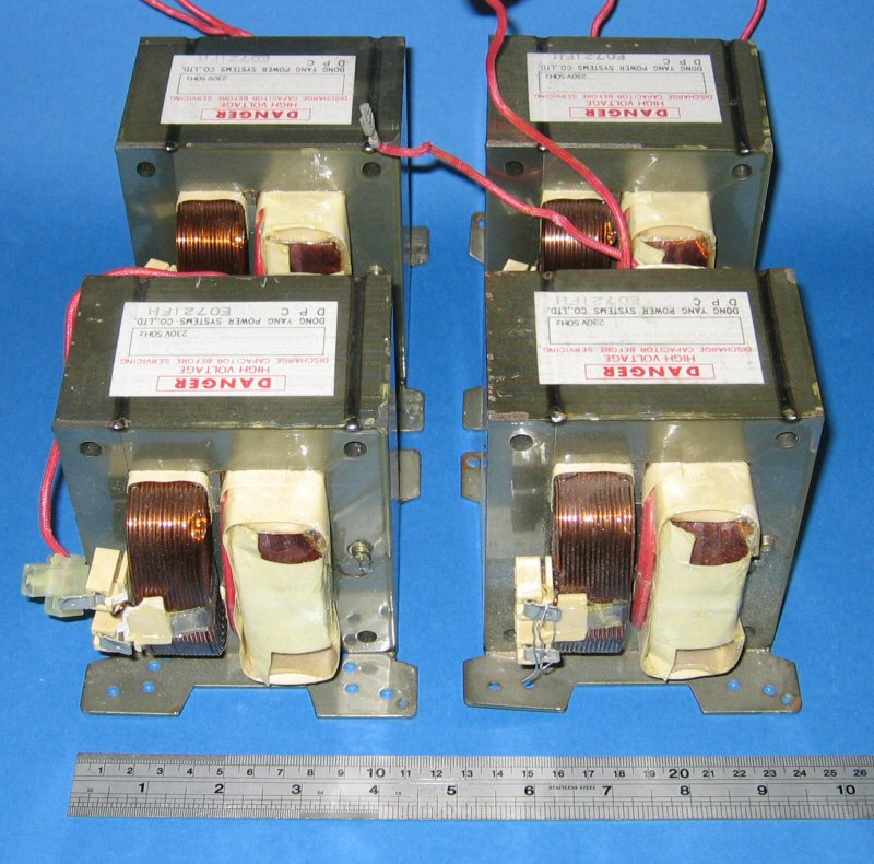
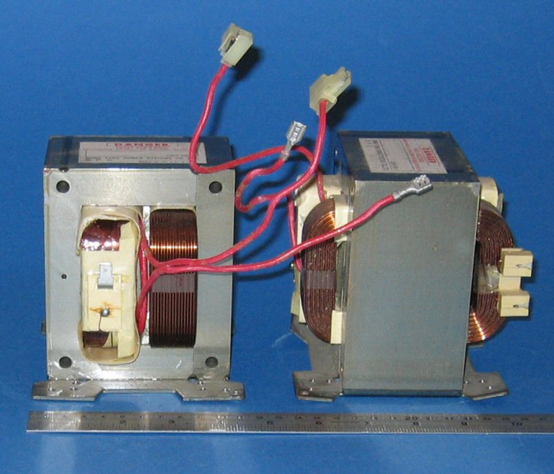
Power Supply
I liked the idea of making my own high voltage power supply, but rather than going to the time and expense of winding high voltage transformers I opted to use 4 MOTs (Microwave Oven Transformers).The primaries are connected in parallel and the secondaries are connected in series. The 2 outer MOTs have there secondaries disconnected from the cores which prevents arcing within the transformers. Normally this type of power supply is submerged in oil to further prevent arcing and aid in cooling, although I'm reluctant to use it as it's heavy and messy. So far I've been using the transformers without any oil and I've not noticed any arcing or heating.
 |
 |
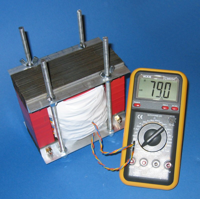
A power supply of this size will easily trip the 13A house breaker, so I've wound a large inductor which acts as a reactive ballast. The inductor is placed in series on the primary side of the MOTs.
 |
 |
| Low Air Gap | High Air Gap |
The inductor was made from a large EI core that I had salvaged from a high current power supply a few months ago. Aluminium L frame was cut to size and drilled to form supports for the laminations. The aluminium L frame is bolted on each side with insulating washers super glued in place to prevent a shorted loop from forming. The E laminations were then blocked together and red insulating tape was wraped around the vertical parts to provide a smooth surface for the coil. The block of I laminations are held in place by threaded rod, which allows them to be moved up and down. This creates an adjustable air gap in the inductors core, which allows me to make changes to the inductance.
The inductor has approximately 200 turns of trifilar wires. Each individual wire is rated at 300VAC @ 6A, which results in a total of 300VAC @ 18A. The wire choosen is far from ideal as it may fail if the core temperature rises, but it was what I already had to hand. If need be I'll replace it with something more suitable at a later date.
The amount of inductance required is around 80mH, which includes the 40mH leakage inductance of the MOTs. That amount of inductance limits the primary side current draw something like 10A. The inductor has been made adjustable so as to allow for a certain amount of tuning.
For power factor correction I'm using 120uF.
| Primary Voltage | 230VAC |
| Primary Current | 10A |
| Frequency | 50Hz |
| Secondary Voltage | 8.8KVAC |
| Secondary Peak Voltage | 12.5KV |
| Secondary Current | 250mA |
| Ballast | Inductor |
| Power Factor Correction | 120uF |
Filtering
The filter between the Tesla coil and the MOT stack is based on the tried and tested Terry Fritz NST Filter.
 |
 |
| Top | Bottom |
Between the mains and the MOT stack I'm using a standard RFI filter wired in reverse. The RFI filter is rated for 16A.
Tank Capacitor
My original plan was to use a large bank of saltwater bottle capacitors.
I used 108 beer bottles with the outside of each bottle being covered in alumnium tape. They were then placed on a wooden platform which had also been covered in aluminium tape. Each bottle was filled with a saturated salt water solution with copper electrodes placed inside.
Originally I had hoped for a capacitance of 80nF but I would have been happy with anything over 40nF. By pure coincedence the measured capacitance of the salt water cap bank was 79nF.
Although the cap bank looked quite good it did have 2 problems. The first problem was corona which could be seen and heard around the top of each bottle (coming of the edge of the tape). The second problem was that the cap bank was left outside which allowed moisture to get inside the wooden frame. As the wooden frame was sat on the floor the high voltage would arc through the wood to the earth. This resulted in smoke and burns to the wood. Both these problems together resulted in a cap bank that couldn't reliably hold its charge. The problem with the arcing to earth is quite easy to fix, but the problem with the corona was less simple. In the end I decided to do away with the salt water capacitor and replace it with an MMC. The salt water capacitor has now been put in the bin.
The MMC uses 80 1.5KV 100nF polypropylene capacitors, which are arranged into 8 banks. Each bank has 10 caps wired in series for a voltage rating of 15KV and a capacitance of 10nF. The banks can be wired in parallel to give a capacitance of 80nF (measured 78nF). Each individual bank can be disconnected which results in a 10nF capacitance reduction.
I quite like the saltwater bottle cap's as they give the Tesla coil a more classic design. Although it should be noted that constructing a saltwater bottle cap is very time consuming and tedious. To construct my saltwater bottle cap I had to cover 108 beer bottles with aluminium tape (after removing the labels) and then saw, hammer and drill 54 copper electrodes and supporting bus bars. Once the saltwater bottle cap is complete and filled with water it's very heavy and impractical. And on top of that, a saltwater capacitor underperforms. An MMC on the other hand is fairly simple to construct and light weight. Also the performance of an MMC is top notch.
Secondary Coil
The secondary coil is wound on 110mm diameter white PVC pipe.
The PVC pipe was first sanded and then coated with insulating varnish. Then 1000 turns of 24 S.W.G. wire was wound on top. Finally the coil had several more coats of insulating varnish applied.
| Diameter | 110mm |
| Height | 560mm |
| D/H Ratio | 1:5 |
| Turns | 1000 |
| Wire Diameter | 0.56mm |
| Wire Gauge | 24 SWG |
| Wire Length | 346,000mm |
| Calculated Inductance | 19.95mH |
| Medhurst K | 0.80 |
| Calculated Capacitance | 8.8pF |
| Calculated Resonant Frequency | 380KHz |
Spark Gap
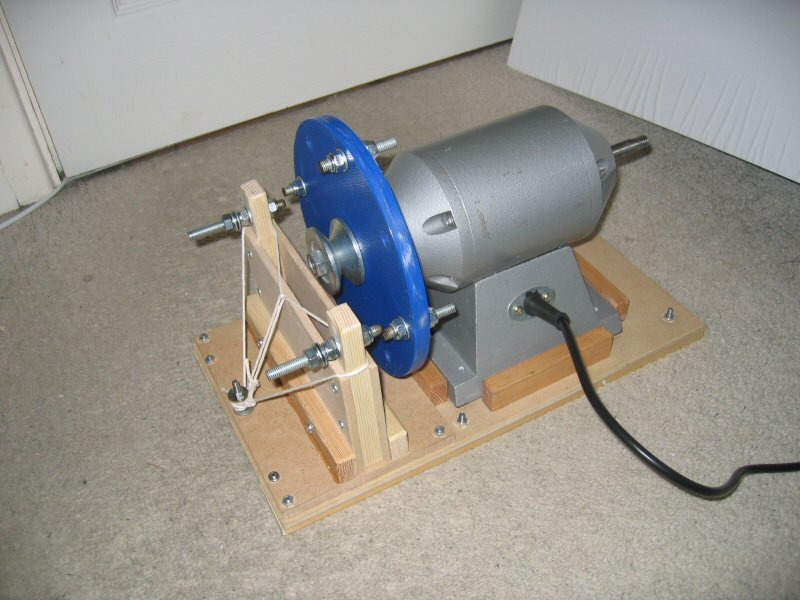
I don't have access to any precision machine tools so my spark gap design is as simple as possible. Initially I was going to use a static spark gap, but after some consideration I decided that it wouldn't require much more effort or cash to construct an asynchronous rotary spark gap. The motor is from a bench top grinder and the disc is made from a 1cm thick blue chopping board. The disc was initially cut with a jig saw and then tidied up by rotating it with the motor while holding a file against it.My first rotary spark gap suffered from vibrations. If the spark gap was shortend the electrodes would sometimes collide and send the wooden supports flying.
That rotary spark gap was scraped and replaced with a more robust version.
 |
 |
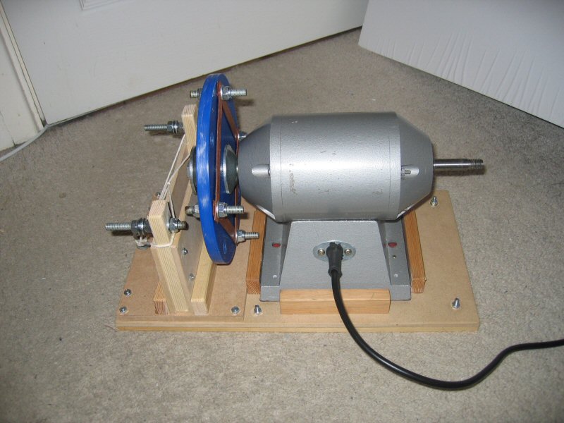 |
So far it's working exactly as it should. The spark gap can be made very small without any electrode collisions. The string pulls the electrodes backwards which stops them vibrating forwards.
The electrodes are made from M8 steel threaded rod. This allows the electrodes to be easily adjusted which is necessary as the disk does not run true. Steel isn't a perfect material for the electrodes but so far it's holding up quite well. I was intending on upgraping to tungsten, but now I'm not sure it's really necessary.
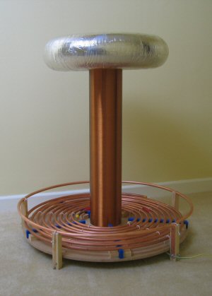
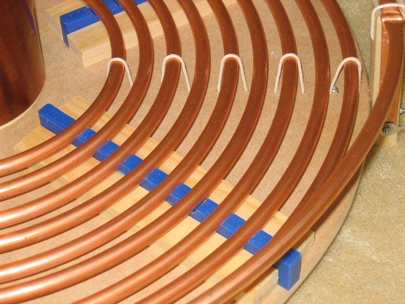
Primary Coil
The primary coil is a flat pancake wound from flexible copper tubing.
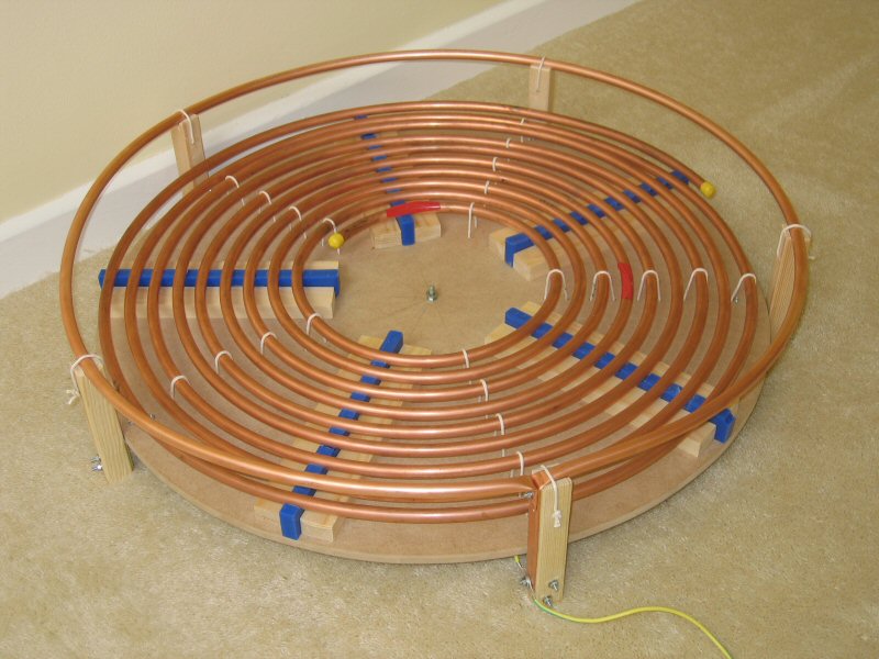
I was worried that the wood would become conductive at high voltages, so I've used blue plastic supprts to raise the coil off the wood. Each plastic support has ditches to hold the primary coil in place. These ditches were made by first drilling 10mm holes in the plastic and then sawing horizontally through each hole. For extra support string has been used to hold the primary coil down.
A strike ring is used which connects directly to the RF ground.
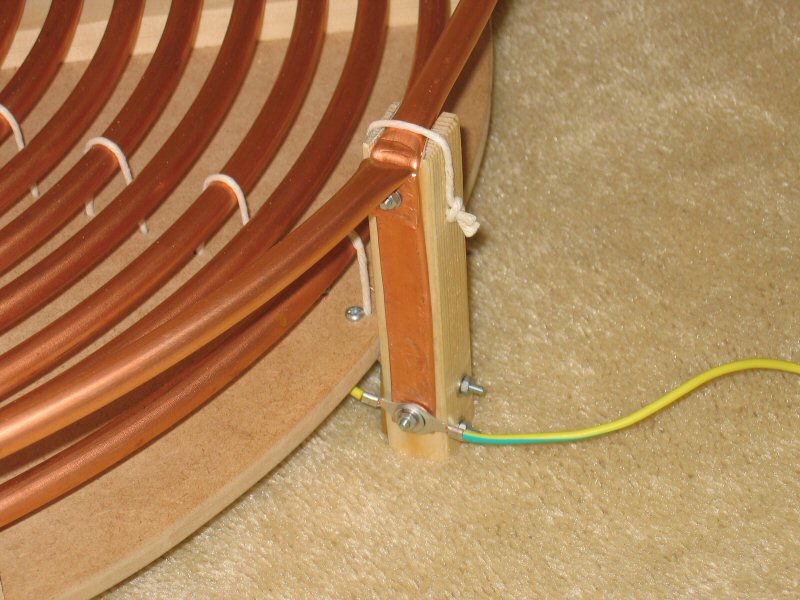
Following a discussion on the Tesla coil mailing list it was pointed out that the strike ring forms a shorted loop. Oops, I hadn't thought of that. For the next run I'll make a gap in the strike ring, which should improve the performance further.
| Conductor Diameter | 10mm |
| Conductor Length | 10m |
| Total Turns | 9 |
| Indside Diameter | 150mm |
| Total Diameter | 550mm |
| Turn Spacing | 10mm |
Top Load
The top load is a toroid made from aluminium ducting, MDF and aluminium tape.

The only draw back to this setup is that it leaks lots of corona. I'm considering spending some money on a spun aluminium toroid.
RF Ground
I haven't really got any suitable RF ground objects near me, so instead, I'll either use aluminium foil or a copper pipe hamered into the ground. Originally I thought the copper pipe in the ground would give the best results, but my SSTC performed better with the aluminium foil. I'll have to investigate this later.Results
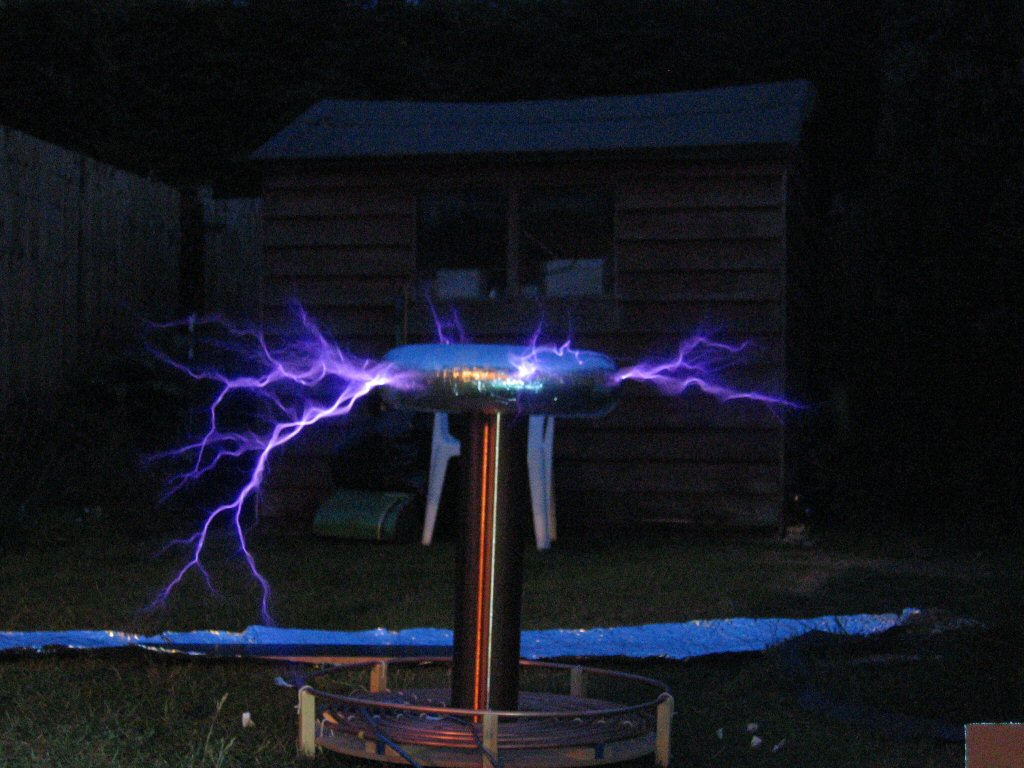
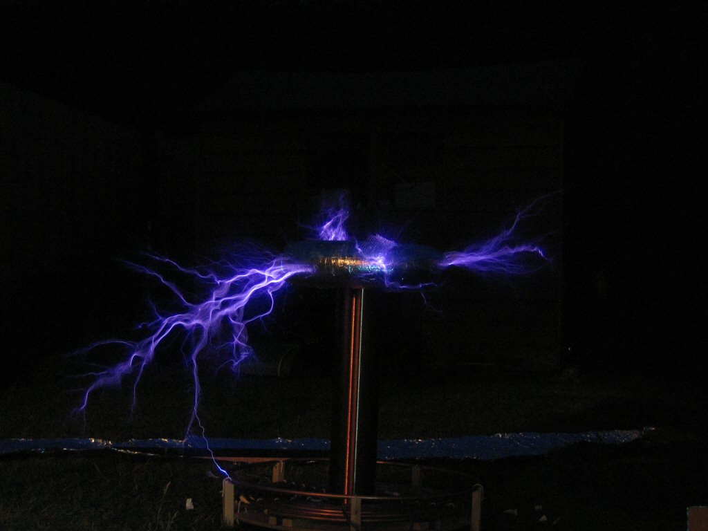
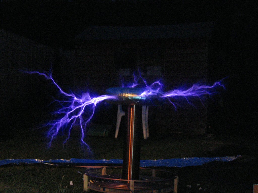
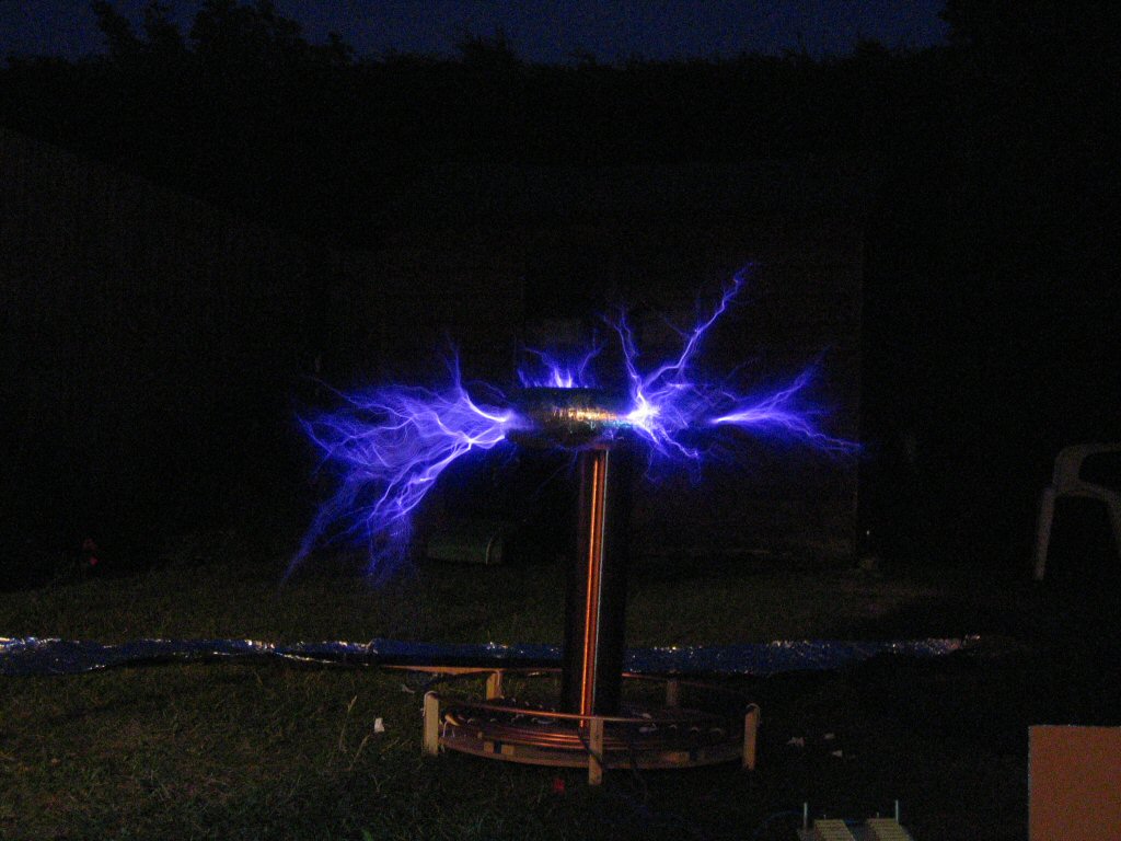
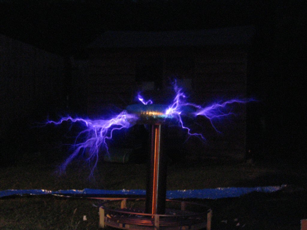
In this section I'll post pictutes of the coil running. To get to this stage I had to redesign the rotary spark gap and tune the coil. The coil still isn't tuned but it is producing visible streamers which is why I'm uploading the following images. You should note that the coil still isn't finished which is why everything is spread out on the floor.
 |
 |
 |
 |
 |
The following thumbnail is a close up of the toroid.
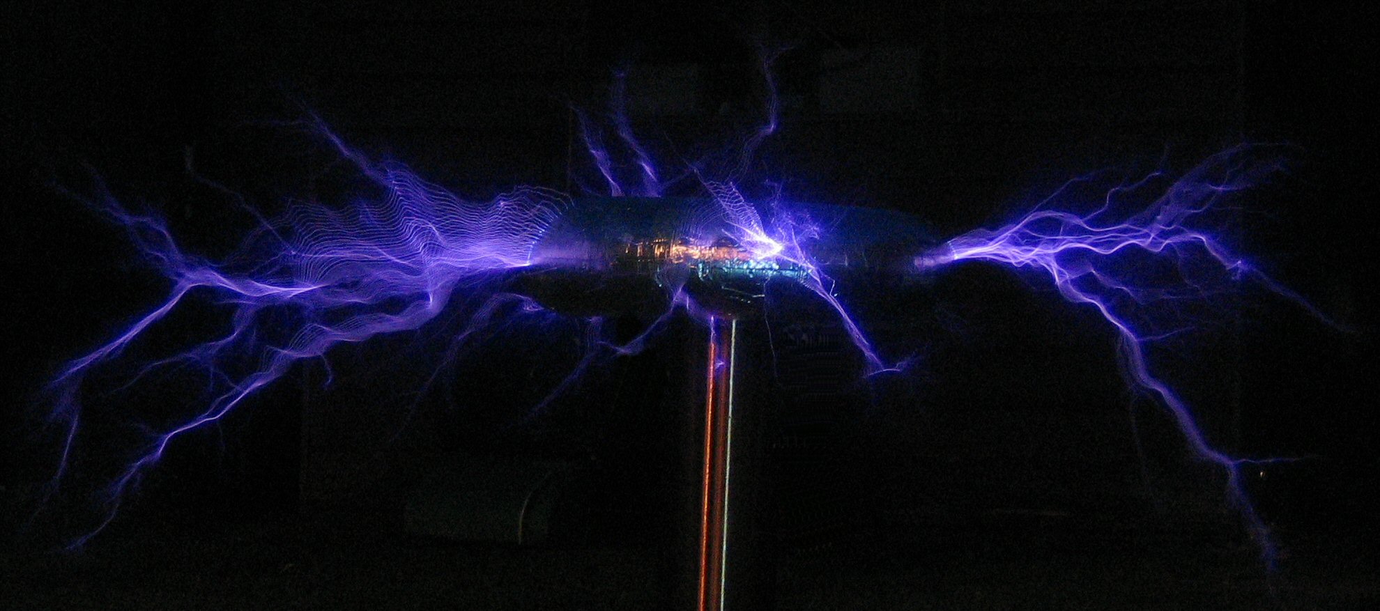
More to come soon...
| Home |