 | Under heavy construction. |
Solid State Tesla Coil
 |
During the early 20th century Nikola Tesla experimented with high voltage high frequency self-resonating air cored transformers. These air cored transformers are now known as Tesla coils. A modern day version of Nikola Tesla's original design is the SSTC (Solid State Tesla Coil). The self-resonating air cored transformer of the SSTC stays true to the original Tesla coil but the tank capacitors and spark gaps have been replaced with solid state components. Although it should be noted that Tesla's original spark gap design can far exceed the power of a modern day solid state design.
The solid state Tesla coil presented on this page is my first coil. It may seem strange to start with a solid state design, rather than a spark gap design, but I find the idea of using modern day technology with Tesla's classic design quite appealing. Also, an advantage to starting with a solid state design was that I already had experience with the solid state side of things as well as already owning the necessary test equipment. I should |
| also say that my SSTC design wouldn't have been possible without modern day Tesla coil pioneers, such as Richie Burnett and Steve Ward, sharing the results of there extensive research. | |
The coil is still under development but I feel it's at a good enough stage to present. This webpage is in its early draft and should hopefully improve as the coil improves.
Some Maths...
This webpage certainly isn't a tutorial on SSTCs, but I feel it's important to show what a balancing act running a Tesla coil is. The following equations give a general idea of how the individual properties of the coil work together.The resonant frequency of the secondary coil can be calculated with the resonant circuit formula:

The frequency (f) is in hertz, inductance (L) is in henrys, and capactiance (C) is in farards. This formula shows that when the capacitance (or inductance) increases the frequency decreases. It's worth noting at this point that capacitance is not just dependent on the toroid, but is also dependent on the surronding environment and the streamers themselves. So should you decide to put your hand close to the Tesla coil while it's running, which I strongly advise you not to do, you will in fact increase the capacitance (by quite a lot as well). Then as you move your hand away the capacitance will decrease. This is one of the reasons why automatic tuning is so desirable.
Wheeler's formula can be used to calculate the inductance of the secondary coil:
The inductance (L) is in microhenry's, radius (R) is in inches, and the width (W) is also in inches. The number of turns is denoted by N.
Medhurst's formula can be used to calculate the secondary coils capacitance:

The capacitance (C) is in picofarads and the diameter (D) is in centimeters. The value K is a constant which is dependent on the ratio of the coils height and diameter. The following table gives some values and google can return others. I'm not how the constants were calculated. I can't find the orignal Medhurst paper. If anyone knows where it is, or knows how the constant are calculated, then please send me an email.
| H/D | K |
| 4.0 | 0.72 |
| 3.5 | 0.67 |
| 3.0 | 0.61 |
| 2.5 | 0.56 |
| 2.0 | 0.50 |
| 1.5 | 0.47 |
| 1.0 | 0.46 |
I'm not sure who's formula this is, but it can be used to calculate the capacitance of a toroid. Again, if anyone knows the details of this formula then please send me an email.
The capacitance (C) is in picofarads, the outside diamater (D1) is in inches, and the diameter of the cross section (D2) is also in inches.
The formulas above are used to calculate the major properties of the secondary coil. It's suprising how close the calculated values are to the measured values. Even after approximations and rounding off the calculated values remain quite accurate.
Setup
| Secondary Turns | 1700 (approx.) |
| Secondary Diameter | 11cm |
| Secondary (coil) Height | 50cm |
| Bridge | Full |
| Primary Coupling | Experimenting |
| Primary Turns | Experimenting |
| Input Voltage | 270VAC via a variac |
| Tuning | Will be automatic |
| Calculated Frequency | 210KHz |
| Measured Frequency | 208KHz |
The Bridge
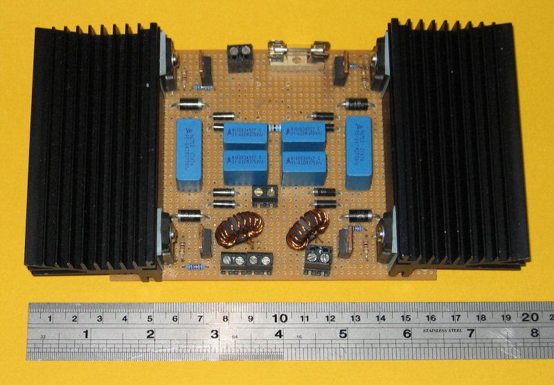
The Bridge uses 4 power MOSFETs in a full bridge configuration. Two GDTs (Gate Driver Transformer's) provide isolation between the driver and the bridge. The GDTs are hand wound with tri-filar windings. Each GDT has 1 input and 2 outputs which are 180o out of phase.
 |
 |
| Bridge Top | Bridge Bottom |
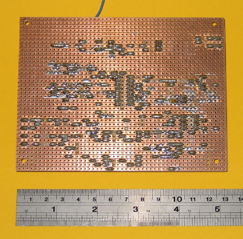
To handle the high voltages and high currents the underside of the bridge uses thick tracks of solder and thick wire. Even the parts that don't see any high voltages have thick solder tracks, which is really just for consistancy.
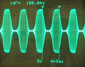
At the moment I use full-wave rectified mains to drive the bridge, but I have also used half-wave rectification.
 |
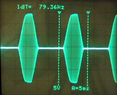 |
| Full Wave | Half Wave |
Full-wave rectification results in thicker arcs and more heat. Infact, with full-wave rectification the copper break-out point usually melts! Some heating on the bridge is also noticed with full-wave rectifcation, but this maybe due to tuning.
Input to the bridge, at the moment, can be a maximum of 270VAC and a suitable quick blow fuse is always used. I run the bridge from a 20A variac which is in turn connected to a very heavy 3KVA isolation transformer. The isolation transformer is mainly to allow me to connect my scope to the bridge while it's running.
The Driver
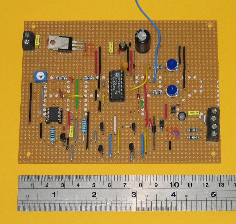
I've tried out 3 different types of driver. The first was manually tuned with a microcontroller (Atmel AVR), the second used a PLL (Phase Locked Loop), and the third used the popular TL494 with a comparator for feedback.The microcontroller based driver provided some initial success, but it lacked resolution and speed. To be honest, I think I choose to use a microcontroller just for the sake of it. I've now abandoned the microcontroller driver in favour of a more suitable setup.
The TL494 driver was developed out of desperation for auto-tuning. In a manual tuning mode it allowed greater flexibility than the microcontroller driver, but I was having some problems with the feedback. I now believe the problems with the feedback were due to too little capacitance on the bridge, which I believe had an effect on the PLL driver.
 |
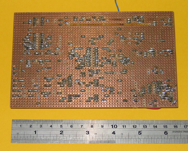 |
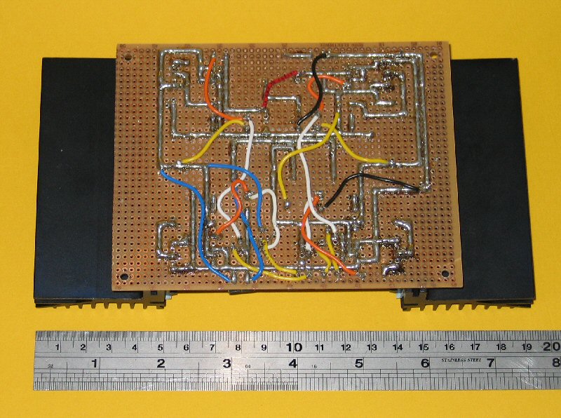
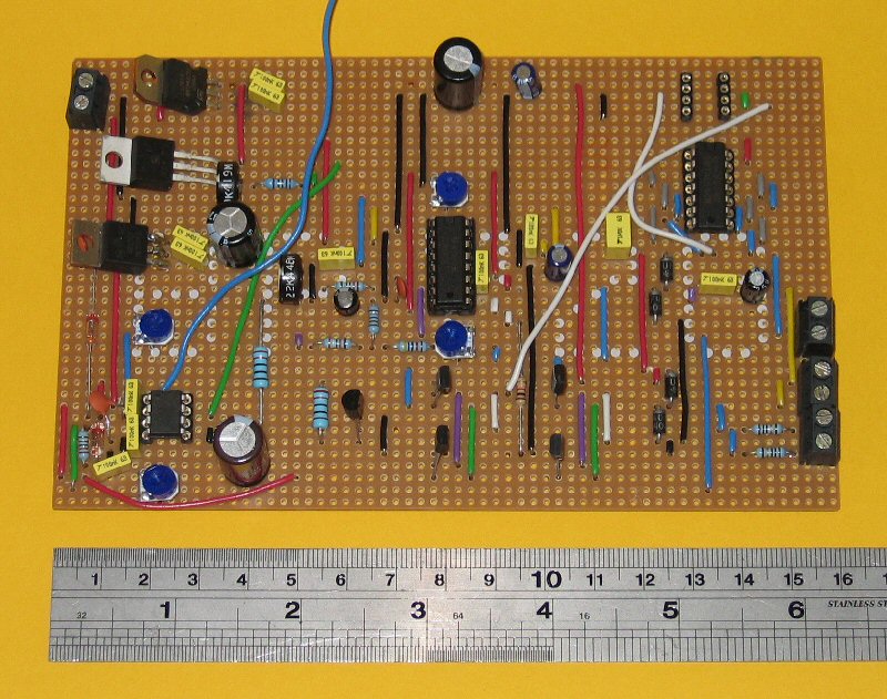
| TL494 Driver Top | TL494 Driver Bottom |
The PLL driver was the second driver developed and worked exactly as it should while connected to a function generator. But I couldn't get it to work with the Tesla coil while the bridge was being run from half-wave rectified mains. However, when I changed the bridge to full-wave mains rectification the PLL could lock onto the Tesla coils resonant frequency. I think if I increase the capacitance on the bridge the PLL will work with half-wave rectifcation. This is still work in progress though.
 |
 |
| PLL Driver Top | PLL Driver Bottom |
All the different types of drivers are powered from the same AC to DC converter. This is simply a fuse, step transformer, 4 diodes and a capacitor. Each driver uses its own voltage regulator.
Originally I was using 4 MOSFET drivers to drive the GDTs, but they kept failing. The cause of the failure was found to be a problem on the full-bridge. As the MOSFET drivers were quite expensive (�5 each) I decided to change to a much cheaper push-pull configuration, which uses transistors. The push-pull setup has taken quite a hammering and hasn't failed yet. For the cost of a single MOSFET driver I could buy loads of transistors.
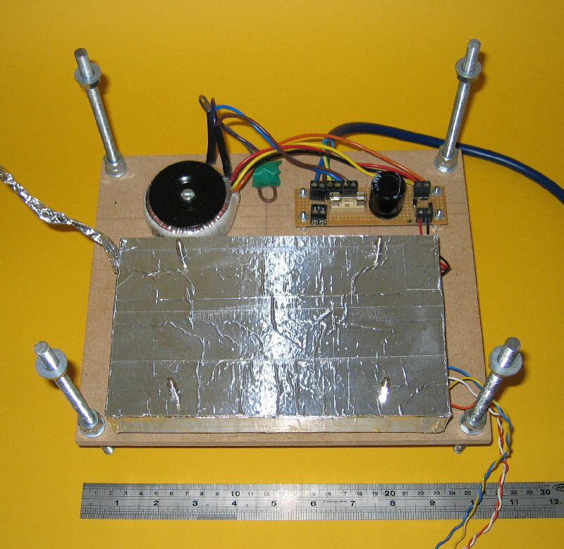
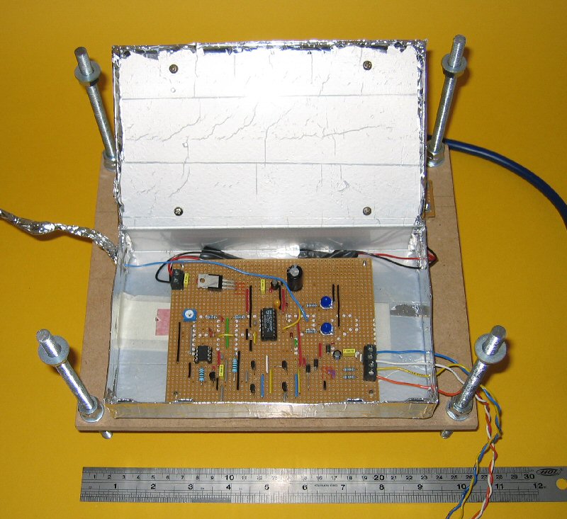
As expected the Tesla coil produces a lot of electromagnetic radiation which causes considerable interference with the driver. The interference is so bad in fact, that the drivers fail to work when the coil is run above a low voltage. For this reason the driver is placed within a shielded box, which happens to be an empty video case convered in aluminium tape. So far the shielded box has fixed all the interference problems. At some point though I'll make a nicer looking box. I haven't found the need to shield the cables going to and from the box, with the exception of the antenna. The bridge sits on top of the shielded box and was orginally interfering with the PLL. By shielding the bottom part of the antenna the problem was fixed.
 |
 |
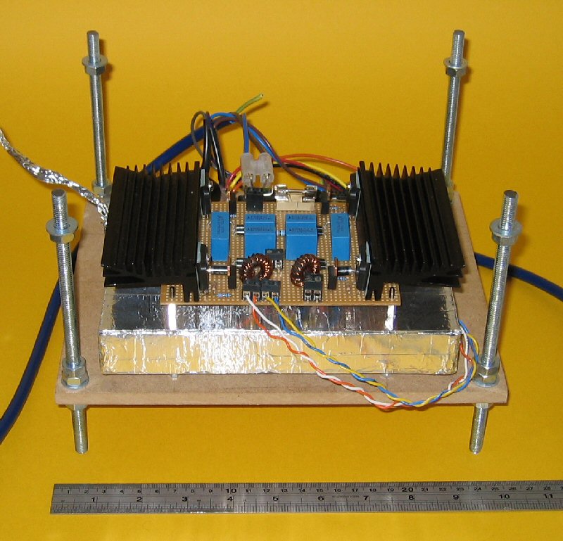 |
| Shielding | Inside Shielding | With Bridge |
The Coils
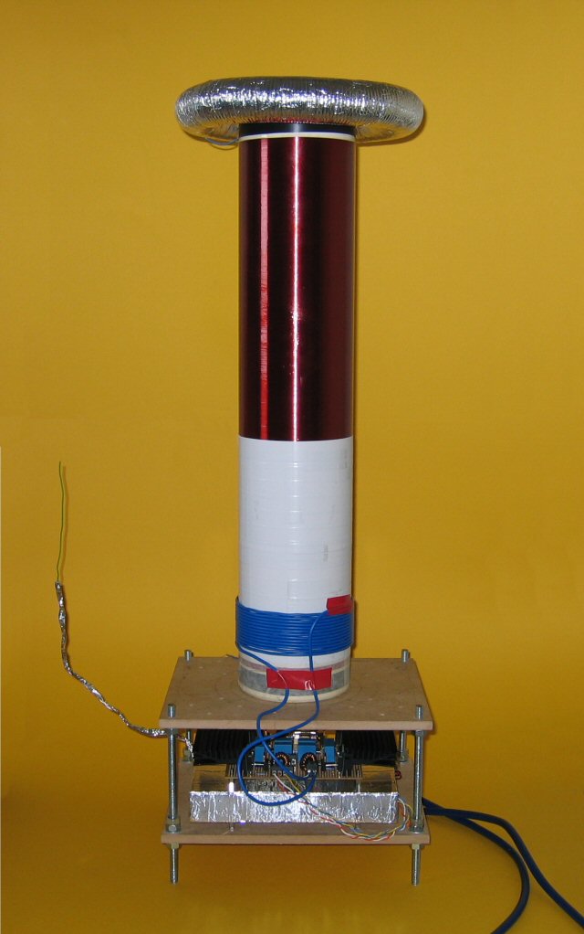
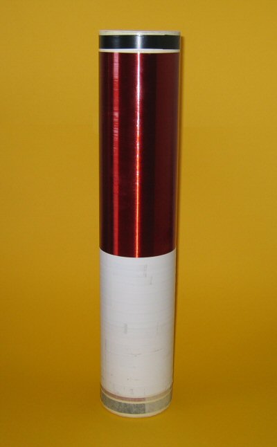
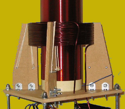
The secondary coil consists of around 1700 turns of 0.25mm copper wire. The diameter is 110mm and the coil height is 500mm. The following image shows the secondary coil. The white material on the bottom half of the coil is to protect it when the primary is wound directly on top of it.
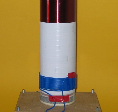
High coupling is definately the best for SSTCs. Low coupling is sometimes necessary with spark gaps, but I can't really see a situation when a solid state design would require low coupling. I've achieved really good results with the primary being wound directly on top of the secondary, but I've noticed some heating at high power levels. By lowering the coupling coefficient by a small amount the heating practicaly disappears.
 |
 |
| High Coupling | Low Coupling |
At the moment I'm still experimenting with the coupling coefficient and the number of primary turns.
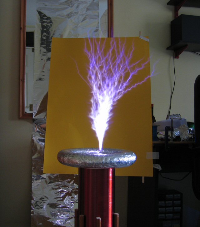
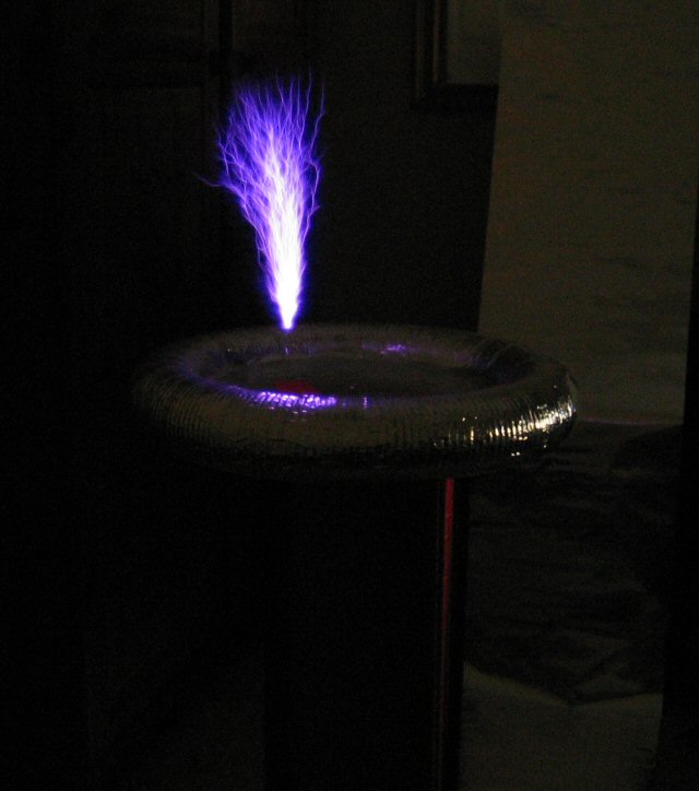
Gallery
 |
 |
 |
 |
 |
Ozone Production An interesting side effect of high voltage discharges, such as from lightning strikes and Tesla coils, is ozone (O3) production. Ozone is an interesting substance as it is highly reactive and very unstable with a short half-life. Humans can detect very small amounts of ozone by smell alone, which gives a sense of freshness. Although I have personally found that the levels of ozone produced by the Tesla coil, in such a small area, tends to be more of a chemical smell rather than a fresh smell. It should be noted at this point that due to its highly reactive nature ozone is in fact toxic and shouldn't really be inhaled.
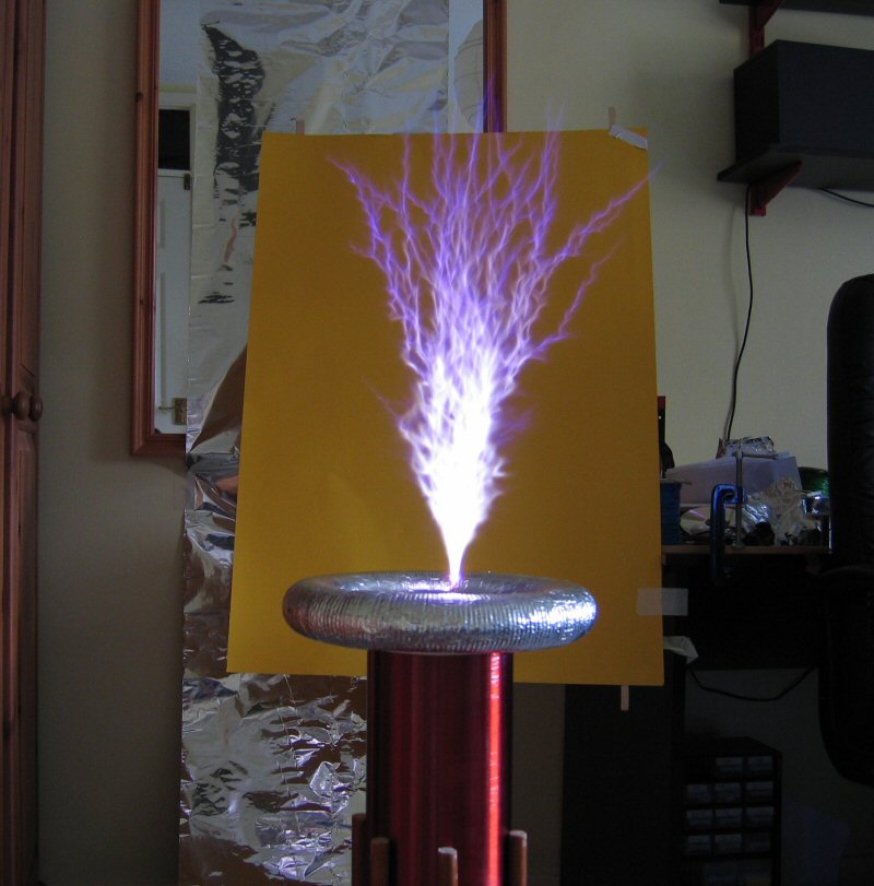
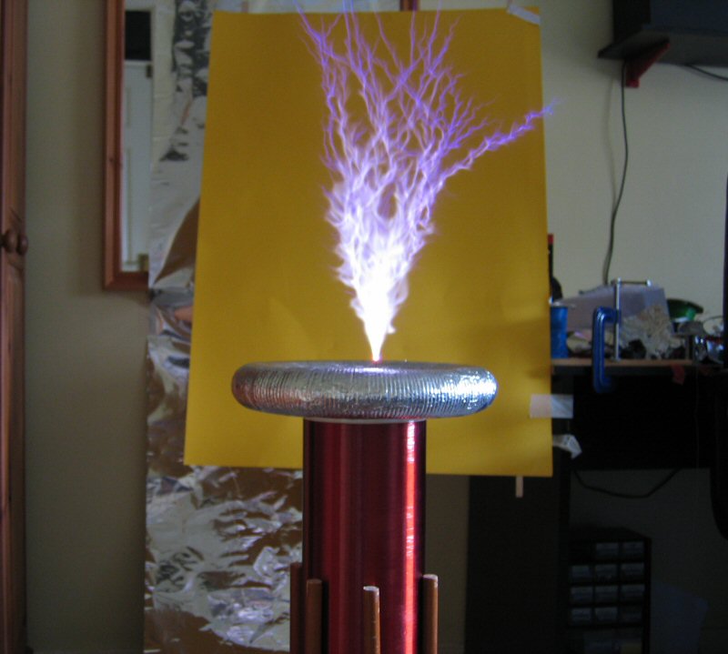
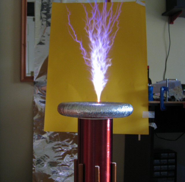
Conclusion In its current state I'm really impressed by the results and it's not even close to performing at its best. The incrediably sharp bright colours of the streamers as it hovers in an almost fixed position is truely amazing and almost mesmerising. The videos and pictures are no where near as spectacular as the real life streamers.
The financial cost of this project has been quite high (actually it's been very high), but I think it's been worth it. I've bought some parts I didn't need and then failed to buy the necessary replacement parts at the start, which resulted in having to spend extra to make up the minimum order price as well as excessive postage and packaging costs. If I were to build the same coil again I'm sure I could do it for a lot less, but that's probably true of any project. You only really know what you need at the start, at the end.
To conclude the conclusion, there's nothing like seeing large streamers appear for the first time. It almost looks alive. I think taking ordinary everyday objects such as water pipe, wood, and copper wire and then putting them together to form a high voltage self resonating system, which is capable of producing etrememly long noisy dangerous streamers, is pretty exciting. And on top of that, it produces ozone!
What Next
As soon as this coil has auto-tuning I think I'll concentrate on a DRSSTC (Dual Resonant Solid State Tesla Coil). After that I would like to construct a large SGTC (Spark Gap Tesla Coil). But rather than buying an NST and tank capacitors I would rather construct my own high voltage power supply and capacitors. An asynchronous spark gap is also quite appealing.
| Home |